EN

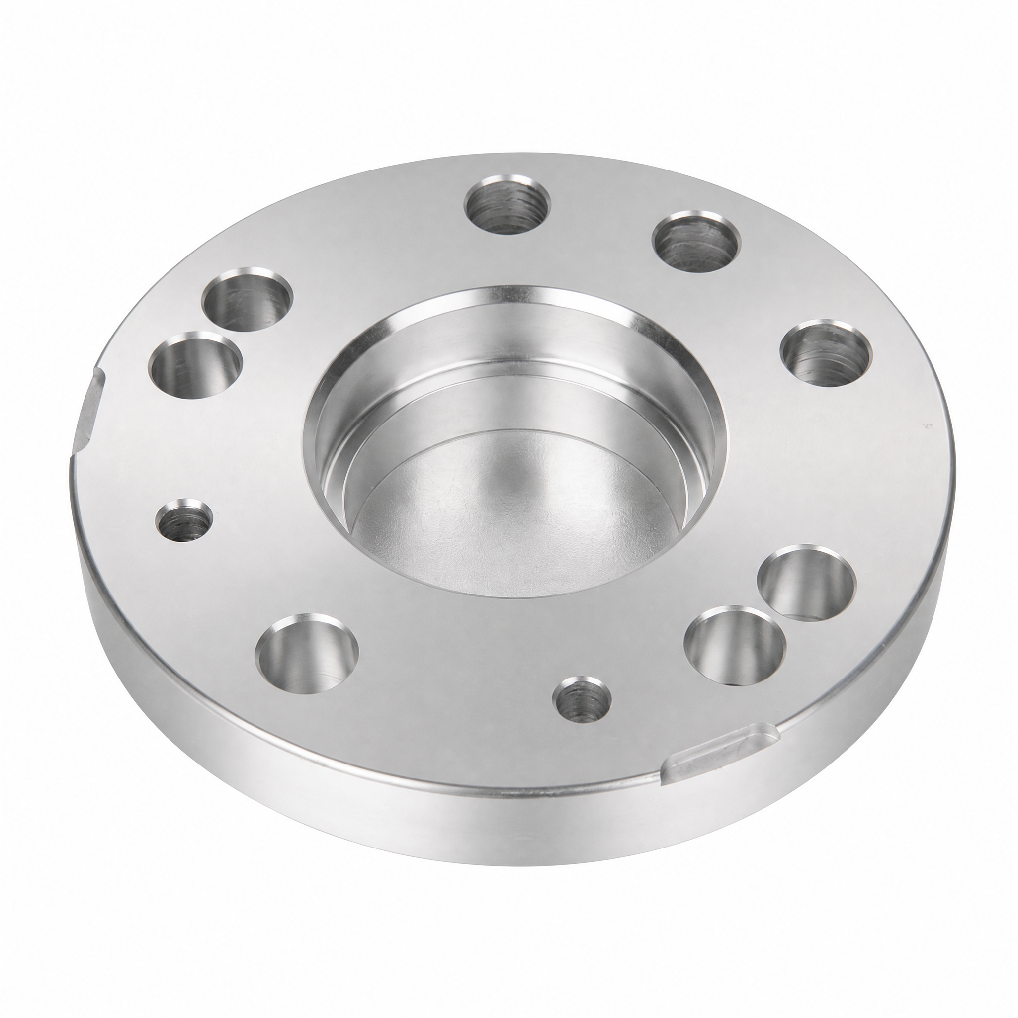
Why Wheel Spacer Installation Requires Precision Offset Planning
Understanding Wheel Offset and Its Impact on Handling, Clearance, and Suspension Geometry
Wheel offset—marked as “ET” followed by a millimeter value—defines the distance between the wheel’s mounting surface and its centerline. Positive offset moves the wheel inward toward the suspension; negative offset extends it outward. This positioning directly affects scrub radius, altering steering responsiveness and straight-line stability. Clearance is equally sensitive: excessive positive offset risks tire contact with struts or brake calipers, while too much negative offset may cause the tire shoulder to rub the fender lip during suspension compression. Subtle changes in the lever arm between hub and contact patch also shift suspension geometry—just 5 mm of offset deviation can accelerate ball-joint wear, increase wheel bearing load, and alter camber gain in corners. These interdependencies make precise offset planning essential before spacer installation.
How Wheel Spacer Adjusts Effective Offset Without Altering Hub or Knuckle Design
A wheel spacer installs between the hub face and wheel, pushing the assembly outward and reducing effective positive offset—without modifying the hub, knuckle, or suspension arms. For example, pairing an ET45 wheel with a 15 mm spacer yields an effective offset of ET30. Because knuckle geometry remains unchanged, camber, caster, and steering axis inclination are preserved; only track width increases. However, the spacer bears full cornering and braking loads, so thickness must ensure adequate hub-centric ring engagement to prevent vibration and uneven loading. High-quality hub-centric spacers align precisely with the hub’s locating lip—transferring weight through the center bore rather than relying on lug studs for alignment. While suspension geometry stays intact, the wider track increases bearing leverage, making accurate final-offset calculation critical to avoid overloading stock components.
Step-by-Step Wheel Spacer Installation: Safety-Critical Protocol
Pre-Installation Verification: Stud Length, Torque Specifications, and Hub-Centric Fit
Before installing a spacer, verify that existing wheel studs provide sufficient thread engagement. Industry best practice requires minimum engagement of 1.5× the stud diameter—for a 12 mm stud, that’s at least 18 mm of threaded length inside the lug nut. A 10 mm spacer, for instance, reduces available engagement by that amount unless longer studs are installed. Always use the vehicle manufacturer’s specified torque value, applied in a star pattern with a calibrated torque wrench. Retorque after 50–100 km, as initial surface settling can reduce clamping force by up to 15% in the first drive cycle. Hub-centric fitment is non-negotiable: the spacer must seat fully on the hub’s central locating ring to carry static and dynamic loads safely. Using a non-hub-centric spacer forces lug studs to bear alignment and shear loads—a leading cause of fatigue failure and harmonic vibration.
When Longer Wheel Studs Are Mandatory—and How to Select the Right Grade 10.9 Replacement
Spacers thicker than 5 mm almost always require longer wheel studs. Factory studs typically lack enough thread length to maintain safe clamping force once spacer thickness is added. Install replacements certified to ISO 898-1:2013 Grade 10.9—guaranteeing a minimum ultimate tensile strength of 1040 MPa. These alloy-steel studs are heat-treated to resist stretching or shearing under the increased bending moments introduced by spacers. Avoid Grade 8.8 or unrated alternatives, which lack the yield strength needed for sustained lateral loading. Match thread pitch (e.g., M12×1.5) and knurl diameter exactly to the original hub specification. Use a proper arbor press—not a hammer—to install press-fit studs, preserving the interference fit integrity. Finally, confirm that extended studs allow full thread engagement within the lug nut, with at least two threads protruding beyond the nut face to ensure consistent clamping across thermal cycles.
Critical Safety Risks and Mitigation Strategies for Wheel Spacer Use
Torque Decay, Thermal Cycling, and Load Distribution: Root Causes of Spacer-Related Failures
Even correctly installed spacers face hidden degradation risks. Torque decay begins immediately post-installation as microscopic surface asperities settle, reducing clamping force. This process accelerates under thermal cycling—repeated heating from brake friction and cooling—which causes differential expansion between aluminum spacers and steel studs. Over time, clamping load can fall below design thresholds without visible warning. Simultaneously, load distribution shifts: spacers increase the bending moment on each stud, concentrating stress at the inner bearing edge unless hub-centric alignment centers and supports the rotating mass. Left unmitigated, these factors promote fastener loosening, resonance, and eventual fatigue failure. Prevention hinges on using hub-centric spacers with Grade 10.9 studs, applying clean, dry threads and calibrated torque, and re-torquing within 50–100 miles to restore clamping integrity after initial settlement and thermal relaxation.
Ensuring Aftermarket Wheel Compatibility with Wheel Spacer
Three-Point Compatibility Check: Bolt Pattern, Centerbore, and Backspacing Alignment
Aftermarket wheel compatibility demands rigorous verification when using spacers. A three-point check prevents clearance conflicts and vibration: First, confirm bolt pattern (e.g., 5×112 mm) matches both hub and wheel exactly—avoid multi-pattern spacers, which compromise structural rigidity. Second, validate hub-centric fit via centerbore: this cylindrical opening is the primary load-bearing and alignment feature. The spacer must match the hub’s diameter, and a precision-machined hub-centric ring must then match the wheel’s bore. Relying solely on lug nuts for centering is a well-documented cause of high-speed vibration. Third, assess backspacing—the distance from the wheel’s mounting surface to its innermost rim edge. Installing a spacer effectively reduces backspacing, moving the wheel outward. In one documented case, a leading performance sedan owner installed 20 mm spacers on wheels with correct bolt pattern and centerbore—yet the inner rim contacted the lower strut mount due to unverified backspacing. Physical test-fitting remains the only reliable method to confirm safe suspension and fender clearance.
FAQs About Wheel Spacer Installation
What is wheel offset, and why is it important?
Wheel offset refers to the distance between the wheel’s mounting surface and its centerline, affecting steering, stability, and clearance. Proper offset planning ensures optimal handling and prevents clearance issues.
Do wheel spacers always require longer wheel studs?
Yes, spacers thicker than 5 mm typically require longer studs to maintain adequate clamping force. Using Grade 10.9 studs ensures durability and safety under increased loads.
How does thermal cycling affect wheel spacers?
Thermal cycling can cause differential expansion between aluminum spacers and steel studs, leading to torque decay and reduced clamping force over time.
What are the major compatibility factors for aftermarket wheels with spacers?
Check bolt pattern, centerbore, and backspacing alignment to ensure the spacer fits securely and provides safe clearance without compromising performance.
What is the difference between hub-centric and non-hub-centric spacers?
Hub-centric spacers align with the hub’s locating lip for load distribution, while non-hub-centric spacers rely on lug studs, increasing the risk of vibration and failure.