EN
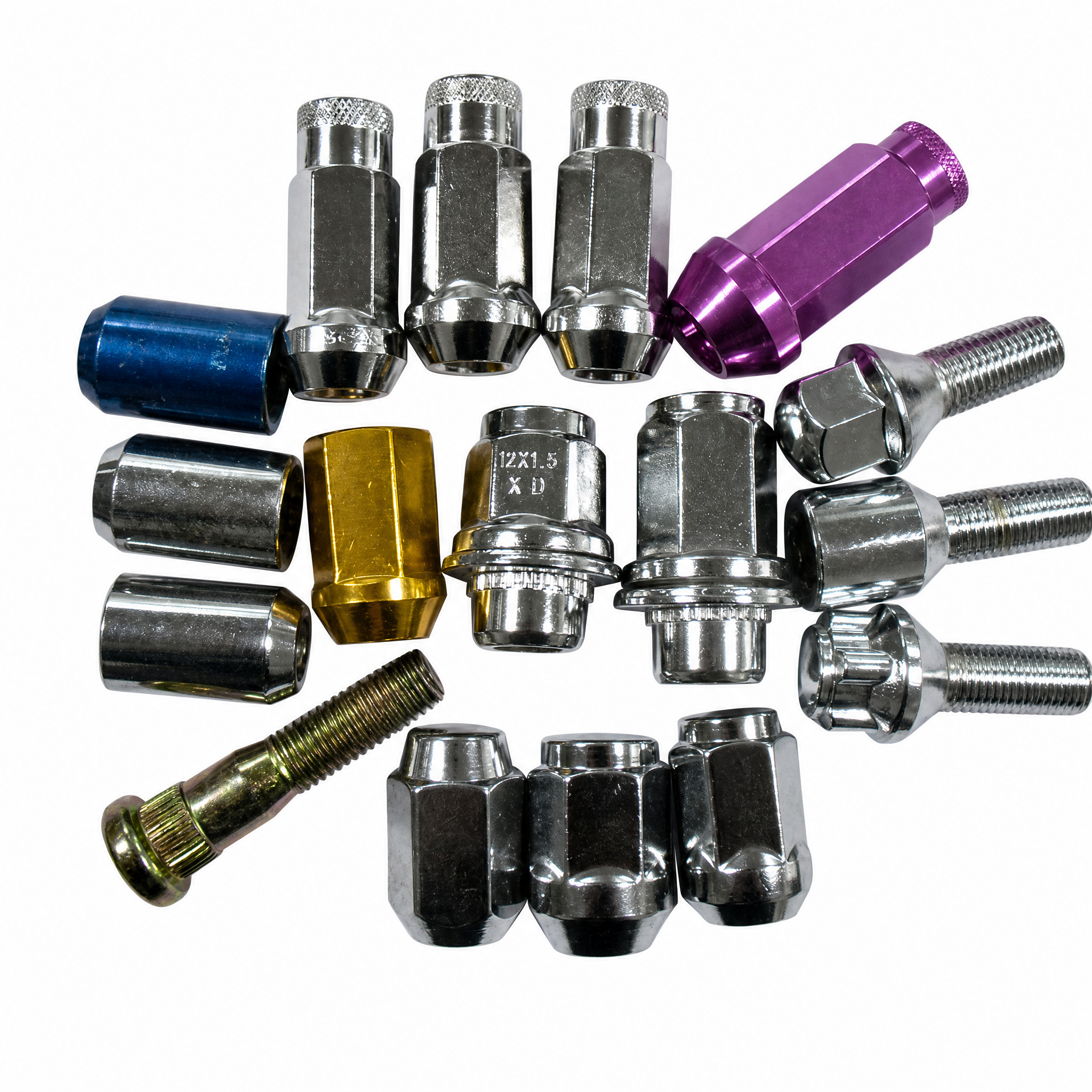
Why Wheel Nut Bolt Custom Sizing Is Critical for OEM Assembly Precision
Vehicle-platform-specific thread dimensions (e.g., M20×1.5, 9/16-18) and their impact on joint integrity
Custom thread dimensions directly determine how clamping force is distributed across the wheel–hub interface. An M20 × 1.5 metric fine thread behaves fundamentally differently from a 9/16‑18 UNF imperial thread in stress concentration, fatigue life, and resistance to self-loosening. In high-volume assembly lines, even a 0.1 mm pitch deviation can reduce preload by 12–15% — a critical loss that compromises joint integrity (VDI 2230, 2022).
The following table summarizes typical automotive thread specifications and their primary effects on joint integrity:
| Thread Size | Type | Pitch / TPI | Typical Hub Material | Preload Sensitivity | Fatigue Class |
|---|---|---|---|---|---|
| M20 × 1.5 | Metric fine | 1.5 mm | Cast iron or forged steel | High (elastic limit) | 10.9 |
| 9/16‑18 | UNF | 18 TPI | Forged aluminum or steel | Moderate | Class 10 |
| M22 × 1.5 | Metric fine | 1.5 mm | Heavy-duty axle steel | Very high | 12.9 |
Thread engagement depth, lead-in angle, and root radius are platform-specific. For instance, a leading light-truck axle manufacturer transitioned from 9/16‑18 to M20 × 1.5 to achieve 22% greater fatigue strength — eliminating field failures linked to loosening. Without custom sizing, factories risk joint separation, galling, or premature bolt fracture.
Two-piece flange designs: Enhancing torque consistency and wheel retention safety in high-volume production
Standard one-piece fasteners often suffer from variable friction at the nut–seat interface, causing torque scatter. A two-piece wheel nut bolt assembly — typically a hardened washer integrated with a rotating nut body — eliminates relative motion between the seating surface and the lug, converting friction torque into repeatable clamp load. In a study by the European Fastener Consortium (2023), two-piece designs reduced torque deviation from ±18% to ±5% across 10,000 cycles.
This consistency is vital on automated lines where pneumatic tools apply a single tightening pass. The integrated flange spreads load evenly, cutting bolt-hole stresses by up to 30%. Because the washer remains static during tightening, paint and debris on the rim are not dragged into the joint — a frequent cause of false torque readings. A major European passenger-car plant reported a 40% drop in wheel-retention audit failures after adopting two-piece flanges, directly linking the design to lower warranty costs and improved safety. For mixed-model lines, standardizing on a two-piece wheel nut bolt across platforms streamlines inventory and torque programming — reinforcing precision in every assembly cycle.
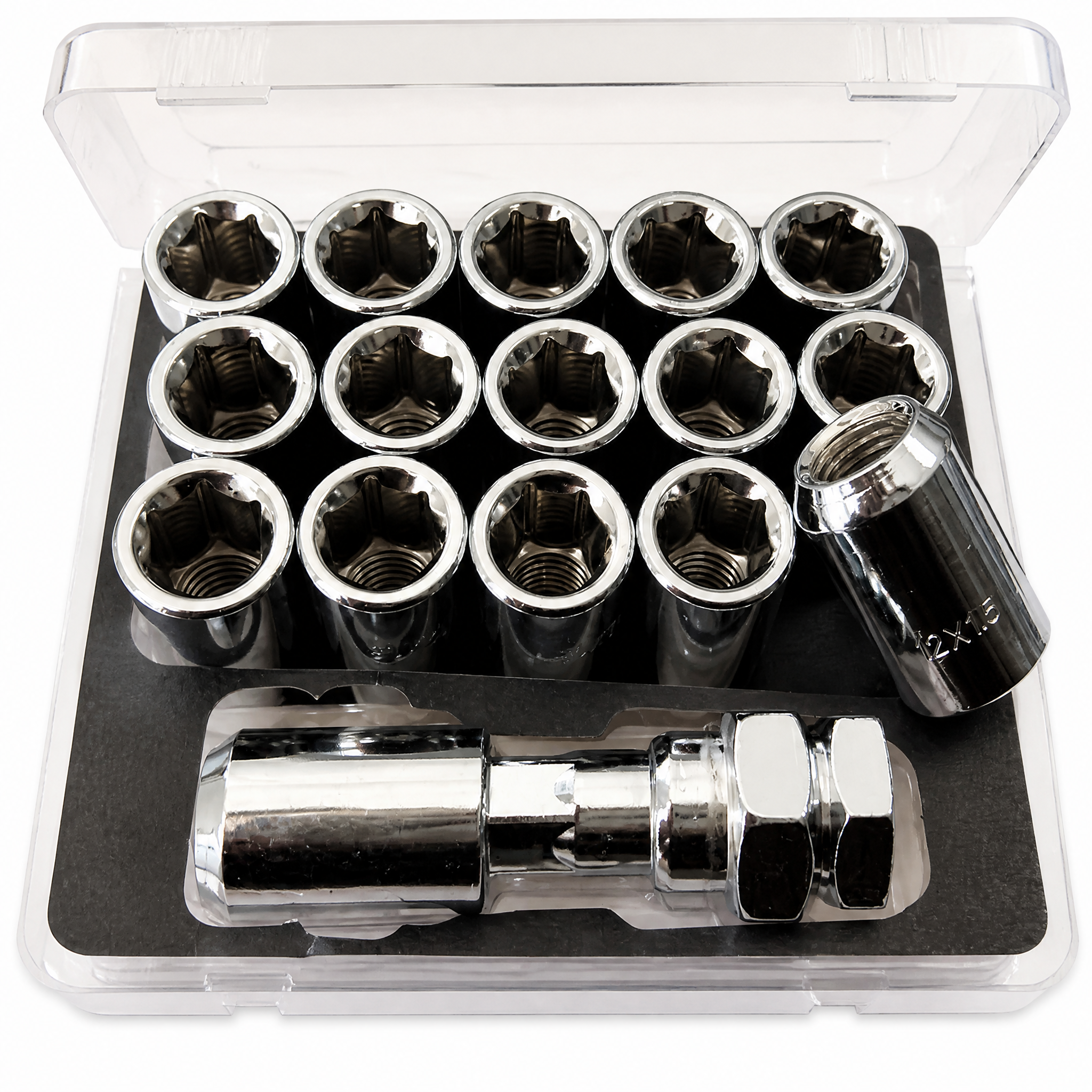
Accurate Wheel Nut Bolt Thread Measurement and Validation Protocols
Dual-standard verification (UTS/ISO) using pitch gauge, digital caliper, and hand-thread check
A single standardized protocol cannot guarantee wheel nut bolt integrity across global supply chains. Dual-standard verification — aligning UTS (Unified Thread Standard) and ISO (International Organization for Standardization) metrics — is the foundation of reliable joint design. The core objective is to eliminate the assumption that a visually similar fastener will mate correctly. For example, an M20×1.5 metric bolt has a defined 60° thread angle and 1.5 mm pitch; a 9/16‑18 UNF bolt, while close in nominal diameter, uses an 18 TPI specification. Mistaking these profiles causes cross-threading and clamp load decay.
The validation process follows a logical, three-tool sequence. First, a calibrated pitch gauge identifies the thread profile by matching its leaves to the threads — immediately distinguishing ISO metric crest geometry from UTS flank form. Second, a digital caliper measures the major diameter with ±0.01 mm resolution, confirming dimensional adherence to the engineering print. The final and most critical step is the hand-thread check: an operator manually threads the wheel nut bolt into a certified master gauge — either a ring gauge for external threads or a plug gauge for internal. This tactile step detects pitch diameter errors invisible to optical scanners, such as minor truncation or lead variation, ensuring the fit is not just dimensionally correct, but functionally seamless.
Resolving the TPI vs. pitch calibration conflict in mass-production QA workflows
The conflict between TPI and metric pitch creates a persistent calibration risk in high-volume wheel nut bolt production. A QA system set exclusively for metric pitch measurements will fail to detect a TPI error because the units are non-proportional. An 18 TPI thread equals a pitch of 1.411 mm — dangerously close to the common M14×1.5 standard (1.5 mm). Relying solely on automated pixel-based sorting can allow this dimensional overlap to pass, creating a latent structural defect. The resolution lies in forcing the QA workflow to baseline every batch by its nominal specification first, before any comparative measurement.
| Calibration Conflict | Root Cause | Measurement Risk | Resolution Protocol |
|---|---|---|---|
| M14×1.5 vs. 9/16-18 | 1.5 mm pitch ≈ 1.411 mm (18 TPI) | Optical sorters accept 0.089 mm variance as tolerance drift | Digital caliper zeroed to target diameter pre-sorting |
| M12×1.25 vs. 1/2-20 | 1.25 mm pitch ≈ 1.27 mm (20 TPI) | Laser micrometer averages profile, masking flank angle mismatch | Master ring gauge go/no-go test every 100 units |
| M20×1.5 vs. 3/4-16 | 1.5 mm pitch ≈ 1.588 mm (16 TPI) | Torque-angle signature begins identically, diverging mid-clamp | Real-time torque curve overlay against ideal master trace |
Direct thread identification prevents the cascade of bad data. Advanced techniques integrate automated optical inspection (AOI) systems that detect 98.7% of surface-level defects — such as cross-threading or form truncation — before a batch reaches the calibration stage. For the wheel nut bolt, an automated laser system with a TPI-to-metric conversion protocol performs a 3-second zone scan, overlaying the measured profile onto a digital master tolerance band derived directly from the SAE standard. This method eliminates operator subjectivity and ensures every fastener is validated against its specific engineering code — not just a generic thread class.
Compliance and Traceability: Matching Wheel Nut Bolt Specifications to SAE and OEM Standards
Ensuring every wheel nut bolt conforms to exact specifications is the foundation of audit readiness and production traceability. The following subsections unpack how strength markings and SAE standards anchor compliance.
Interpreting strength grade markings (Grade 10.9, Class 10) as compliance anchors for audit readiness
Interpreting strength grade markings on a wheel nut bolt is a fundamental audit checkpoint. Metric Grade 10.9 denotes a minimum tensile strength of 1000 MPa and a 900 MPa yield (ISO 898-1:2023). Nuts marked Class 10 must pair with these bolts to maintain consistent proof loads. During a production audit, quality engineers cross-reference head markings against the material certificate and the control plan. A mislabeled Grade 8.8 bolt provides roughly 20% less clamping force — a deviation that could lead to wheel detachment. Factories embed optical character recognition in inline vision systems to validate every bolt before assembly, establishing a traceability chain that proves only compliant wheel nut bolts enter the line — simplifying audit evidence.
SAE J995, J417, and J1835 — how standards govern wheel nut bolt material, heat treatment, and testing
SAE J995, J417, and J1835 form the backbone of wheel nut bolt compliance in North American manufacturing. SAE J995 defines mechanical and material requirements for steel nuts, ensuring the nut’s proof load and hardness match its bolt counterpart. SAE J417 standardizes hardness measurement via Rockwell and Brinell methods, preventing soft or brittle parts from entering torque-critical joints. Meanwhile, SAE J1835 directly governs wheel nut bolts and studs: it sets dimensional tolerances, thread fit, and fatigue performance targets, and mandates a residual clamp load test after torque cycling. Under these standards, every production lot undergoes tensile and metallographic examination, creating an unbroken audit trail. Additionally, J995 mandates proof-load testing of nuts to 1.1 times the bolt’s minimum tensile strength to prevent stripping. This layered verification guarantees that each wheel nut bolt withstands dynamic loads, corrosion, and repeated assembly without failure — satisfying both OEM quality audits and regulatory demands.
Lug Nut vs. Lug Bolt: Strategic Implications for Wheel Nut Bolt Selection in Automated Assembly
The lug nut system — where a nut threads onto a fixed stud protruding from the hub — differs fundamentally from a lug bolt assembly, which integrates the stud and nut into a single fastener that screws directly into the wheel hub. In automated production, this distinction drives critical decisions around wheel nut bolt selection, tooling design, and quality assurance. With a stud-based system, the wheel can be hung on the exposed studs before fasteners are applied, providing natural alignment that simplifies robotic vision guidance and reduces insertion failure rates. Conversely, lug bolts must be individually aligned with the hub’s internal threads, requiring end-effectors to simultaneously grip the bolt head and manage axial rotation — a process more prone to cross-threading if positioning tolerances drift even slightly.
Takt time and parallel processing capacity further separate the two approaches. Multi-spindle nut runners can simultaneously tighten all lug nuts on a single wheel, compressing the fastening step into seconds. Lug bolt lines often demand a sequential start-and-torque cycle for each fastener, increasing per-station cycle time and potentially creating bottlenecks. Automation engineers must also weigh changeover complexity: while wheel nut bolt thread sizes and seat geometries may vary between models, the stud pattern remains fixed, allowing quick tooling swaps for nut-only configurations. Maintaining torque accuracy is equally vital; studs transmit the clamping force directly to the hub, whereas lug bolts concentrate stress at the bolt-to-hub interface, demanding more rigorous angle-monitored fastening strategies to prevent premature loosening in high-volume output.
Compliance and traceability remain constant across both architectures — any wheel nut bolt must meet the strength and dimensional standards of SAE J995 or equivalent OEM specifications — but the assembly sequence and error-proofing protocols diverge. Poka-yoke sensors for stud presence or bolt-insertion depth become essential, and inline torque audit systems must adapt calibration curves for the unique frictional behavior of each joint type. Ultimately, the choice is not merely mechanical; it shapes the entire automated assembly layout, from material handling logistics to the number of robotic stations, and directly influences overall equipment effectiveness in a modern auto manufacturing factory.
FAQ Section
What is the significance of custom thread dimensions?
Custom thread dimensions ensure the proper clamping force distribution across the wheel–hub interface, impacting joint integrity and fatigue life. A small deviation can critically compromise assembly precision.
What are two-piece flange designs?
Two-piece flange designs integrate a hardened washer with a rotating nut body, reducing torque scatter and enhancing wheel retention safety. They are particularly effective in high-volume automated production lines.
How is thread measurement validated?
Thread measurement validation involves using dual-standard verification with tools including pitch gauges, digital calipers, and hand-thread checks to ensure dimensional and functional fit.
What are SAE standards for wheel nut bolts?
SAE standards like J995, J417, and J1835 govern material composition, heat treatment, mechanical properties, and testing protocols for wheel nut bolts, ensuring compliance and traceability.
What is the difference between lug nuts and lug bolts?
Lug nuts attach to fixed studs protruding from the hub, offering natural alignment, whereas lug bolts integrate the stud and nut, requiring precise insertion and alignment, impacting automated assembly design.
Table of Contents
- Why Wheel Nut Bolt Custom Sizing Is Critical for OEM Assembly Precision
- Accurate Wheel Nut Bolt Thread Measurement and Validation Protocols
- Compliance and Traceability: Matching Wheel Nut Bolt Specifications to SAE and OEM Standards
- Lug Nut vs. Lug Bolt: Strategic Implications for Wheel Nut Bolt Selection in Automated Assembly
- FAQ Section